
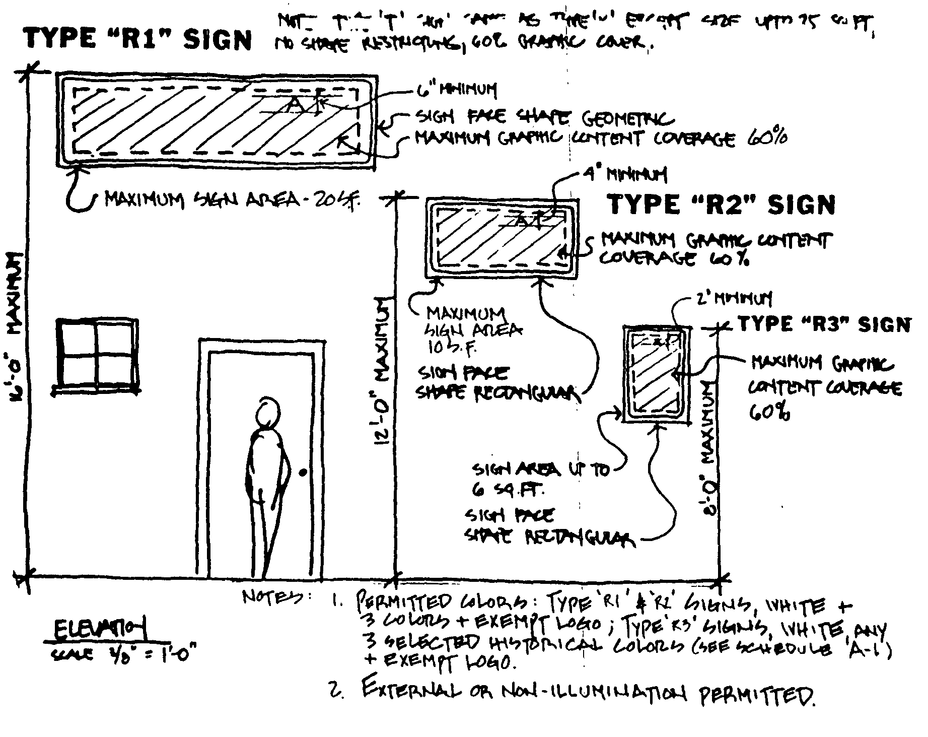
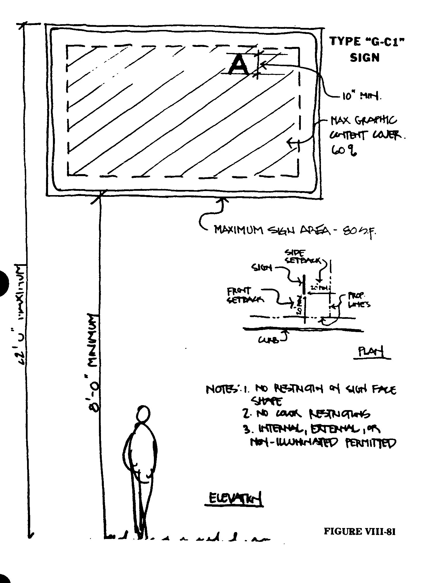
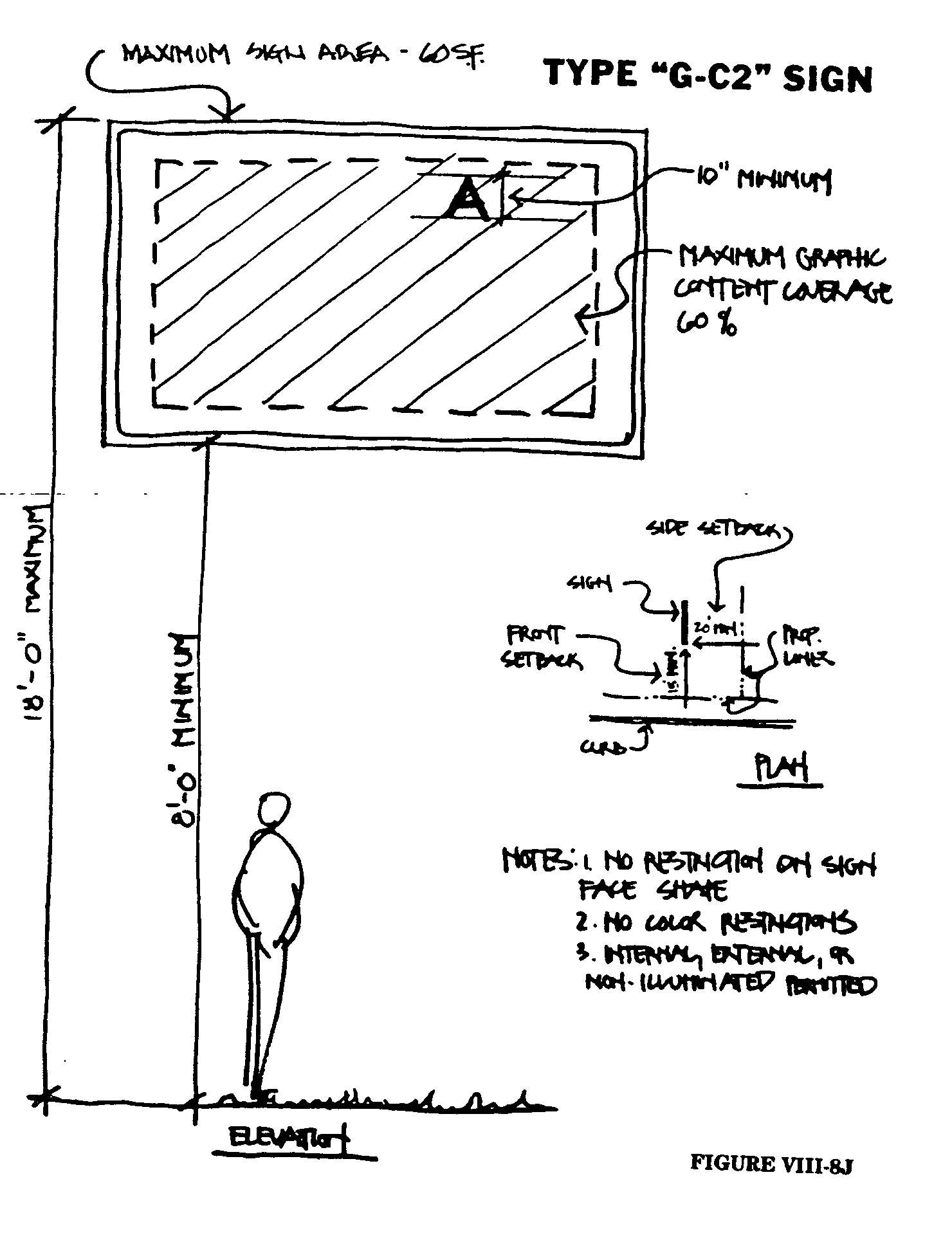
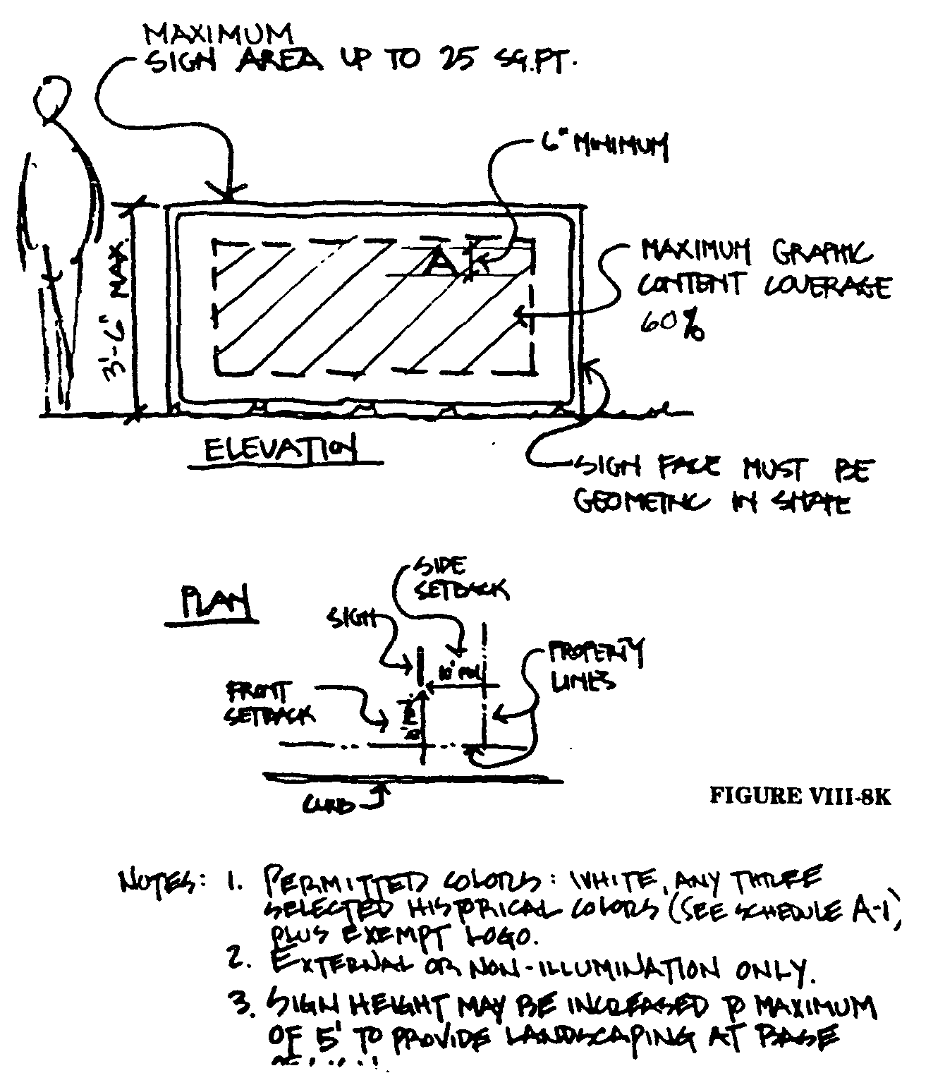
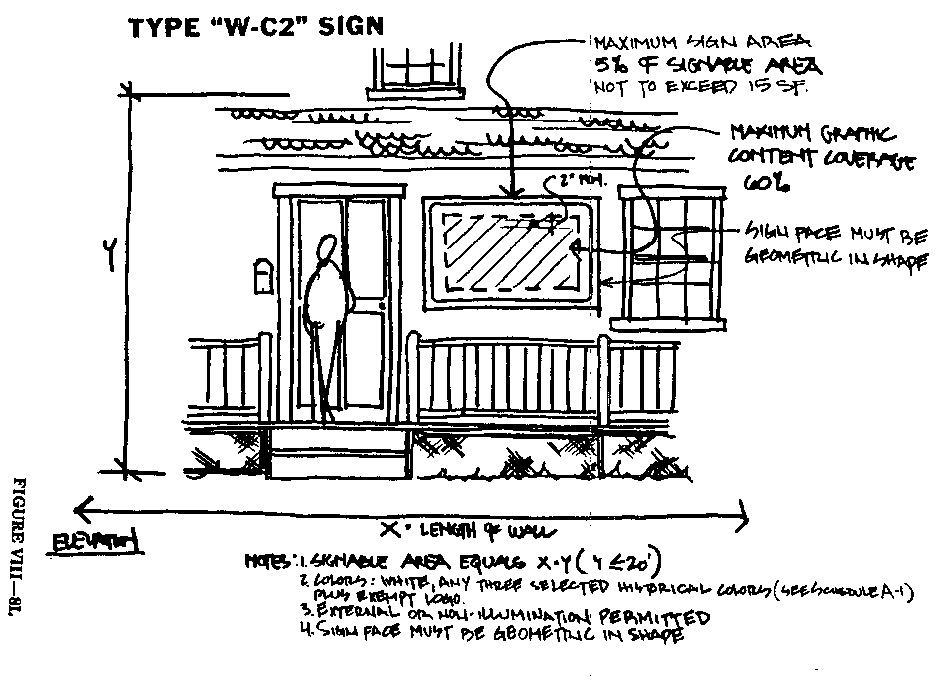
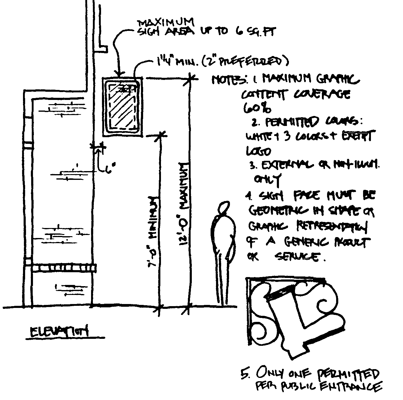
These Selected Historical Colors are specified by code number selected from Federal Standard 595 and are illustrated by a selection from a group of "Williamsburg" paint colors manufactured by Martin Senour Paints, 1370 Ontario Avenue, N.W., Cleveland, Ohio, 44113. Paint from any source substantially complying with the colors standard numbers shown may be utilized. It is not intended to encourage the use of any particular manufacturer. The Martin Senour "Williamsburg" paint color chart is on file in the office of the Administrative Officer for review by applicants or other interested parties:�
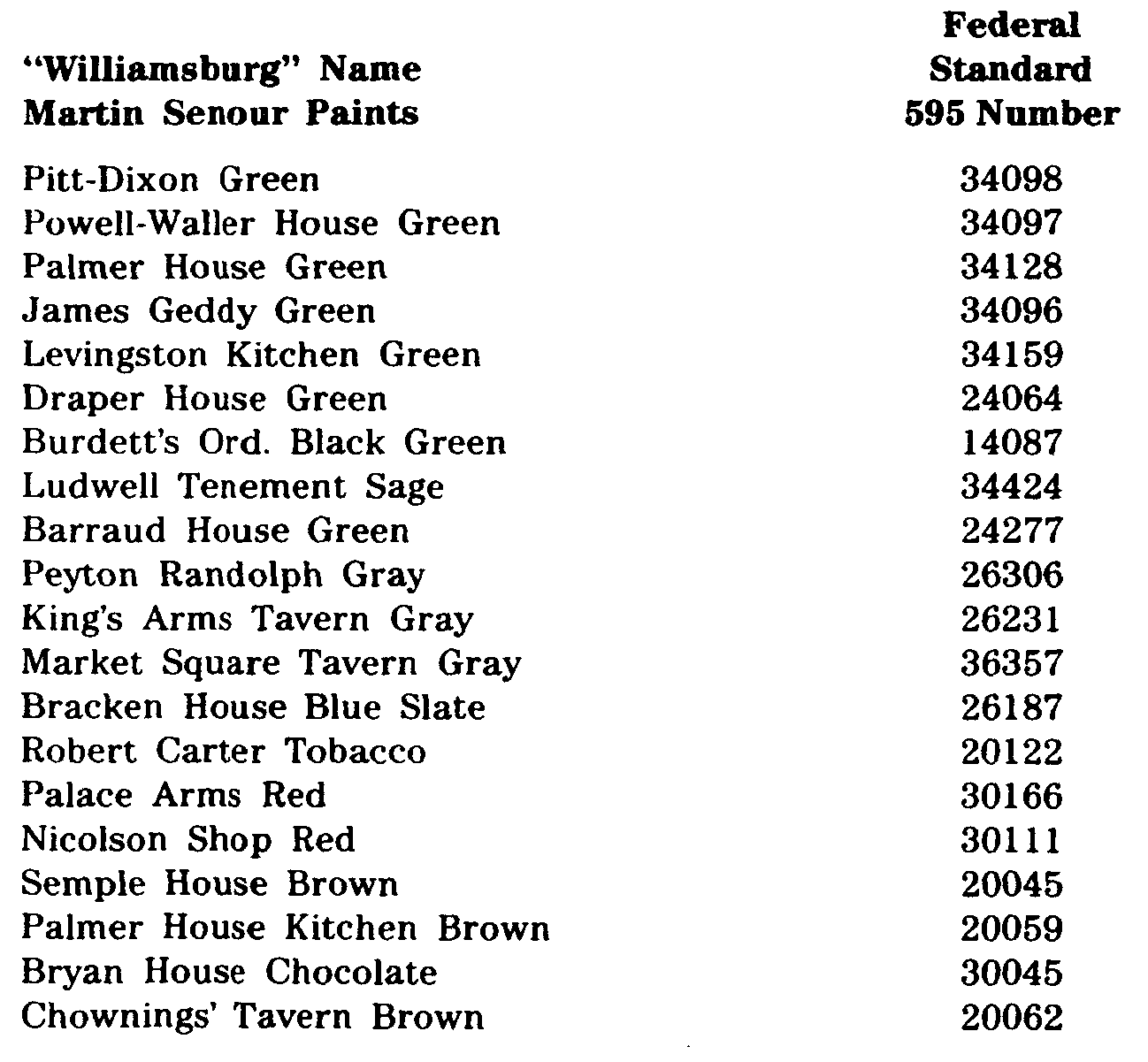
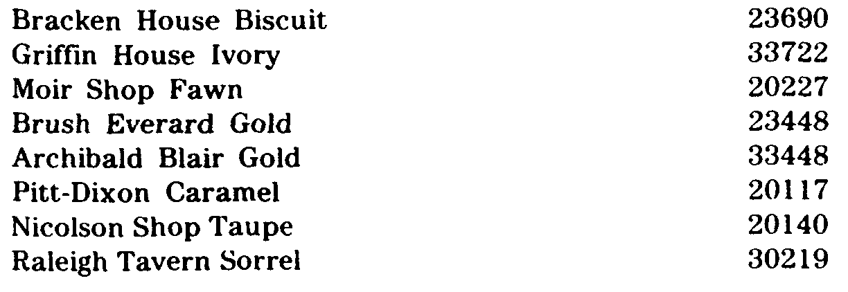
Note: Silver or Gold Leaf is also a "Selected Historical Color."�
Solid wastes from all uses other than single or two (2) family homes, if stored outdoors, shall be placed in metal receptacles within a screened refuse area subject to the following minimum standards:�
a. The screened refuse area shall not be located within any front yard area.�
b. The refuse storage area shall be surrounded on three (3) sides by a solid uniform fence or wall not less than five (5') feet nor more than eight (8') feet in height. Such fence shall be exempt from the provisions of any ordinance of the Borough regulating the height of fences and requiring permits therefor.�
c. A five (5') foot minimum width landscaping area shall be provided along the fence or wall enclosing the refuse storage area. The landscaping to be provided shall be shown on the site plan submitted for Planning Board approval.�
d. The opening in the enclosed refuse area should be located to minimize the view of refuse from adjoining properties or public streets.�
e. If located within or adjacent to a parking area or access drive, the enclosed refuse areas shall be separated from such parking area or access drive by curbing.�
f. The enclosed refuse area shall not be located so as to interfere with traffic circulation or the parking of vehicles.�
g. All refuse shall be deposited in containers maintained within the refuse area. No containers shall be maintained anywhere on a site except in a refuse area meeting these requirements.�
h. If outdoor storage of solid waste is not proposed, the site plan submission shall detail the methods proposed for accommodating solid waste within the structure. The Municipal Agency may require that a suitable area be set aside, but not improved, for a future solid waste storage area meeting these requirements even if indoor accommodation for solid waste are proposed.�
(Ord. #686, S 13-8.28)�
a. General Requirements. All storm drainage facilities shall be constructed in accordance with the applicable requirements of the Standard Specifications. The developer (or his engineer) shall submit complete calculations, specifications, plans and details for all proposed storm drainage facilities. Any field samples or laboratory tests required to document the conclusions of such calculations shall be formed at the sole expense of the developer.�
b. Storm Drain Pipe. All storm drain pipes shall be either slip joint type reinforced concrete or, subject to the restrictions herein, fully coated, invert paved, corrugated metal steel culvert pipe meeting the requirements of the Standard Specifications and of a wall thickness sufficient to meet the proposed conditions of service; but in any event, no wall thickness less than Class 3, Wall B, for concrete pipe or No. 14 gauge for corrugated metal steel pipe shall be allowed. Generally, concrete pipe will be used except in areas of steep grades or other restrictive physical conditions where corrugated metal or other types of pipe may be permitted. No concrete pipe may be laid on grades exceeding ten (10`x) percent. Concrete pipe below thirty (30") inches (or equivalent) in size will be jointed using a mortared joint in accordance with the specifications. Concrete storm drain pipes, thirty (30") inches or larger in diameter, will be jointed using a preformed bituminous mastic pressure-type joint sealer or rubber-ring-type or other equivalent approved joint. All corrugated metal pipe shall be fully bituminouscoated with paved invert and of a gauge meeting the requirements of the Standard Specifications sufficient for the proposed service. Where conditions permit, corrugated aluminum storm drains may be substituted for corrugated metal steel storm drains where the same is otherwise permitted on the basis of an equivalent three (3) edge bearing or crushed strength. Substitution on an equivalent gauge basis will not be allowed. All storm drains shall be tangent between inlets, manholes or other structures, except that the use of fittings or factory curved or mitered pipe may be allowed by the Borough Engineer when necessary to accommodate existing geometry or utilities. Prior to laying any storm drains, the bottom of all trenches shall be inspected by the Borough Engineer. Should the Engineer determine that the trench is unsuitable for the placement of the pipe, the developer shall take all necessary action to remove or eliminate any unsuitable conditions. These may include, but are not limited to, excavation and backfilling with suitable material, placement of bedding material, construction of pipe cradles or such other action necessary to remove all unsuitable conditions. Proposed storm drainage installations which do not conform to the above must be fully detailed and approved as part of the final plat.�
c. Inlets and Manholes. Inlets and manholes shall be constructed where required in accordance with the requirements of the Standard Specifications and Standard Construction Details.�
d. Headwalls. All pipe terminations shall be provided with poured concrete headwalls, precast concrete and sections or corrugated metal end sections in accordance with the approved final plat. Poured concrete headwalls shall be wing-type headwalls with aprons in accordance with the Standard Construction Details.�
e. Inlet and Manhole Location.�
1. In continuous conduit runs, spacing between structures (inlets or manholes) shall not exceed six hundred (600') feet.�
�
2. Structures (inlets or manholes) shall be located so as not to interfere with primary routes of pedestrian travel or any proposed handicapped ramp or similar facility.�
3. In general, surface flow length, for flow of four (4) or more cubic feet per second, on paved surfaces shall not exceed seven hundred fifty (750') feet, provided that:�
(a) Gutter flow widths on local and local collector streets shall not exceed eleven (11') feet, or such narrower width as may be necessary to provide a twelve (12') foot wide clear lane in the center of the roadway.�
(b) Gutter flow width on minor collector streets shall not exceed nine (9') feet, or such narrower width as may be necessary to provide two (2) twelve (12') foot wide clear lanes in the center of the roadway.�
(c) Gutter flow widths on major collector streets without shoulders shall not exceed five (5') feet, or such narrower width as may be necessary to provide four (4) ten (10') foot wide clear lanes in the center of the roadway.�
(d) Gutter flow widths on minor and principal arterial streets and major collector streets with shoulders shall be retained within the shoulder areas.�
(e) Swale gutter flow widths in parking areas shall not exceed twelve (12') feet.�
(f) Gutter flow widths shall provide for the maintenance of two (2) ten (10') foot wide clear lanes in all access and major circulation drives and one (1) twelve (12') foot wide clear lane in all other aisles in all parking areas, except as otherwise provided in Subsection 25-8.29e.7.�
4. Maximum design capacities which may be used to determine actual inlet location and spacing are:�
(a) Not in Sump Conditions�
Type B 4 cubic feet per second�
Type E (in paved areas) 4 cubic feet per second�
Type E (in yard areas) 1.5 cubic feet per second�
(b) In Sump Conditions�
To be individually de signed�
5. Only Type B inlets shall be used in curbed roadways or curbed access or major circulation drives.�
6. Generally, sufficient inlets will be placed to eliminate any flow exceeding two (2) cubic feet per second across any intersections.�
7. Parking areas may be designed to allow ponding in order to decrease intensity of runoff. In such case, ponding will not be allowed in any access or major circulation drive or in any area of heavy pedestrian activity and shall not exceed six (6") inches at any point calculated for the appropriate design storm in accordance with Subsection 25-8.29h.1 and shall meet the criteria set forth in Subsection 25-8.29h.11.�
f. Type of Inlets and Manholes. All curb inlets shall be New Jersey Department of Transportation Standard Type B and all yard inlets shall be Standard Type E; all manholes shall be New Jersey Department of Transportation standard four (4') foot diameter, unless a larger diameter is necessary. Casting heights on curb inlets shall be two (2") inches greater than the specified curb face, and the gutter shall be properly transitioned approximately ten (10') feet on either side of the inlet.�
g. Open Channels.�
1. Open channels shall be designed to contain the required flow and shall have a design velocity low enough, in the judgment of the Borough Engineer, to prevent erosion. The minimum easement for open channel sections shall be the maximum design top width of the channel section segment plus twenty- five (25') feet rounded to the next highest five (5') foot increment. The excess easement area shall be provided offset to that side of the channel most convenient for use by maintenance crews. The minimum distance between the channel top edge and any easement line shall be five (5') feet. Excess velocity, if any, as determined by the Borough Engineer, in open channels must be controlled by sod, rip-rap, paving, ditch checks or other suitable methods. Changes of direction in open channels must have a maximum radius of eight hundred (800') feet or be adequately paved or rip-rapped.�
2. Generally, unlined open channel cross-sections shall have side slopes not steeper than four to one (4:1) for channel depths of two (2') feet or less than not steeper than eight to one (8:1) for channel depths of more than two (2') feet. Lined open channel side slopes shall not be steeper than two to one (2:1).�
3. The bottoms of all unlined open channels and the channel side slopes, to at least the design flow level, will be sodded with suitable coarse grass sod.�
4. All unlined open channel side slopes above the design minimum flow level will be topsoiled and seeded or otherwise suitably stabilized in accordance with an approved soil disturbance permit.�
5. All unlined open channels which can be expected to have a base flow of five (5) cubic feet per second or more for at least two (2) out of every twelve (12) months will be provided with a low flow channel using gabions, rip-rap, lining, one-third pipe sections or other arrangements approved as part of the final plat submission.�
h. Minimum Basis for Calculations.�
1. Design Storm Frequency:�
(a) For closed conduits, five (5) years; or if the above results in a conduit size at least equivalent to a twenty-one (21") inch reinforced concrete pipe, then ten (10) years; or if the above results in a conduit size at least equivalent to a thirty (30") inch reinforced concrete pipe, then twenty-five (25) years; or if the above results in a conduit size at least equivalent to a fifty-four (54") inch reinforced concrete pipe, then fifty (50) years.�
(b) For open channels, ten (10) years; or if the tributary area exceeds fifty (50) acres, then twenty-five (25) years; or if the tributary area exceeds two hundred fifty (250) acres, then fifty (50) years. The flooding limits for storms with a return period of twice the design storm shall be determined for all open channels. Such limits shall be the drainage or conservation easements delineated on the plat.�
(c) For detention facilities, a twenty-four (24) hour flood with a return period not less than fifty (50) years or, if the tributary area exceeds fifty (50) acres, then one hundred (100) years.�
(d) For retention facilities, double the capacity obtained by applying the requirements for detention facilities.�
(e) For gutter flow calculations, ten (10) years for local, local collector and minor collector streets, twenty-five (25) years for major collectors and minor arterials and fifty (50) years for principal arterials.�
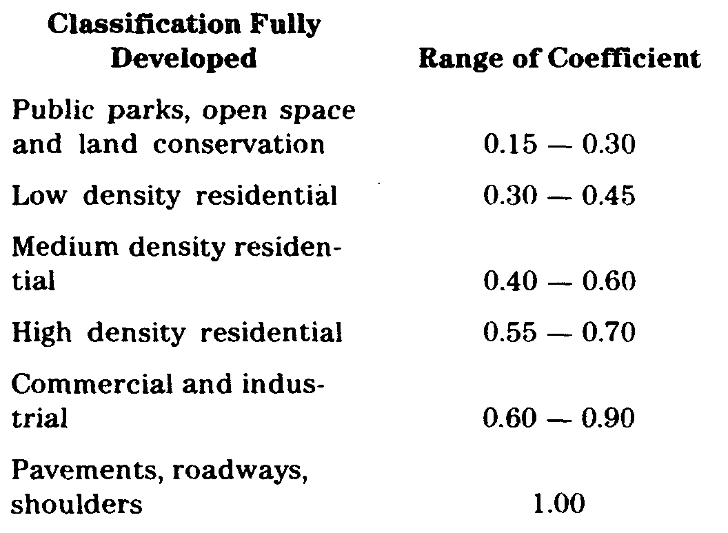
2. Runoff Calculations: Runoff determinations should be made using the rational formula or, in unusual cases, other methods with the prior approval of the Borough Engineer. Upstream areas should be considered based on their full development potential according to current zoning or the current use, whichever produces the greatest runoff. Runoff coefficients used should generally fall in the following ranges:�
3. Velocity Restriction:�
(a) In general, velocities in closed conduits at design flow should be at least two (2') feet per second, but not more than that velocity which will cause erosion damage to the conduit. In general, velocities in open channels at design flow shall not be less than one-half (1/2) foot per second and not greater than that velocity which will begin to cause erosion or scouring of the channel. For unlined earth channels the maximum velocity allowed will be two (2') feet per second. For other channels sufficient design data and soil tests to determine the character of the channel shall be made by the developer and shall be made available to the Borough Engineer at the time of drainage review.�
(b) At transitions between closed conduits and open channels or different types of open channels suitable provisions must be made to accommodate the velocity transitions. These provisions may include rip-rapping, gabions, lining, aprons, chutes and checks, or others, all suitably detailed and approved as part of the final plat submission. For all flow of forty (40) cubic feet per second or more, tailwater depth and velocity calculations shall be submitted.�
4. Design Formulas and Friction Factors: In general, the Manning formula will be used by the Borough Engineer to review the adequacy of proposed drainage facilities. Other formulas may be used in particular cases with the previous agreement of the Board. A friction factor (n) of twelve-thousandths (0.012) will be used for nonporous concrete pipe; a factor of twenty-thousandths (0.020) will be used for fully coated corrugated metal pipe with paved invert. Commensurate factors will be used for other pipe type or shapes. A friction factor (n) not less than twelve-thousandths (0.012) will be used for fully lined concrete channels; a factor not less than twenty-five thousandths (0.025) will be used for good earth channels and a factor not less than one hundred thousandths (0.100) will be used for fair to poor natural streams and water courses. Commensurate factors will be used for other channel types.�
5. All drainage facilities carrying runoff from tributary areas larger than one-half (1/2) square mile must have the approval of the New Jersey Division of Water Policy and Supply.�
6. All encroachments of natural waterways must be referred to the New Jersey Division of Water Policy and Supply for approval in accordance with statute. The State may retain jurisdiction in which case a permit will be necessary as set forth above or may refer the matter to the County Engineer for review.�
7. All non-pipe culvets shall be designed for AASHO H20-44 loading. All culverts of any type shall be carried to the roadway right-of-way and shall terminate with headwalls or other approved end treatment. All conduits terminating or beginning in open channels shall be provided with headwalls or other appropriate end treatment.�
8. Guardrails and/or railings shall be placed at all drainage structures where the interests of pedestrian or vehicular safety would dictate. The Municipal Agency may require that any open channel, other than naturally occurring streams, be fenced with chain link fencing forty-eight (48") inches high if the banks of the channel are steeper than one (1') foot vertically for every four (4') feet horizontally and either the total depth of the channel exceeds four (4') feet, or the channel would be expected to have a depth of flow greater than two (2') feet more often than once every ten (10) .years. For maintenance purposes, gates may be required by the Municipal Agency at approximately two hundred (200') foot intervals.�
9. Storm drainage systems shall be designed to include not only the proper drainage of the actual area of the specific development and the area tributary thereto, but shall also include the disposal of the stormwater runoff to an adequate outlet or other means of final disposal of the stormwater, such as an ocean, river, running stream, lagoon or an existing adequate storm sewer.�
10. The use of siltation and oil separation basins with controlled outflows will be required to prevent pollution of waterways when discharge is into a lagoon, bay or other standing body of water.�
11. Whenever sump conditions occur, an analysis shall be made of the effect of the occurrence of a major storm having at least one-hundred (100) year return frequency. The effect of such storm and the flooding limits anticipated shall be shown. Site design, grading and drainage, shall anticipate such major storm and be so arranged so as to prevent damage to existing or proposed structures or adjacent properties under such conditions.�
12. All drainage arrangements (either piped or overland flow) for sites on County roads or State highways shall be approved by the County Engineer or the New Jersey Department of Transportation, respectively; in addition to being acceptable to the Municipal Agency.�
i. Special Drainage Provisions.�
1. The existing system of natural drainage within each development shall be preserved to the maximum extent possible. To this end, the Board may require the preservation of natural drainage swales, recharge areas, wet weather ponds and similar features and may require suitable drainage and conservation easements and possible increases in lot size to allow usable lots with the preservation of such features.�
2. Subject to review and approval by the Board, the design of the development may be modified to take advantage of the natural drainage features of the land. In such review, the Board will use the following criteria:�
(a) The utilization of the natural drainage system to the fullest extent possible.�
(b) The maintenance of the natural drainage system as much as possible in its unimproved state.�
(c) When drainage channels are required, wide shallow swales with natural vegetation will be preferred to other sections.�
(d) The construction of flow retarding devices, detention areas and recharge berms to minimize runoff value increases.�
(e) Maintenance of the base flow in streams, reservoirs and ponds.�
(f) The reinforcement, improvement. and/or extension .of the natural drainage system to such an extent as is necessary to eliminate flooding and excess maintenance requirements.�
3. All developments or portions or total schemes of development which, based upon the preliminary plat submission, total fifteen (15) or more acres will be expected, to the extent that the Board considers possible, to limit the total stormwater runoff from the site after development to not more than one hundred fifteen (115%) percent of the runoff from the site in its undeveloped state. The utilization of the provisions of this section to limit such runoff are encouraged. However, the Board may require the use of reasonable artificial methods of detention and/or recharge if it determines that natural provisions are not feasible. The Board may waive the provisions of this section if the nature of the development, the character of adjacent previously developed areas or other factors make the utilization of natural drainage features or runoff limiting devices inadvisable or impractical.�
(Ord. #686, S 13-8.29)�
�

