Inlets shall be provided to control the shoulder encroachment and water velocity.�
2. Swales adjacent to shoulders�
When swales are provided in cut areas, the water shall not encroach upon the roadway area during a 10-year frequency storm of 5 minute duration.�
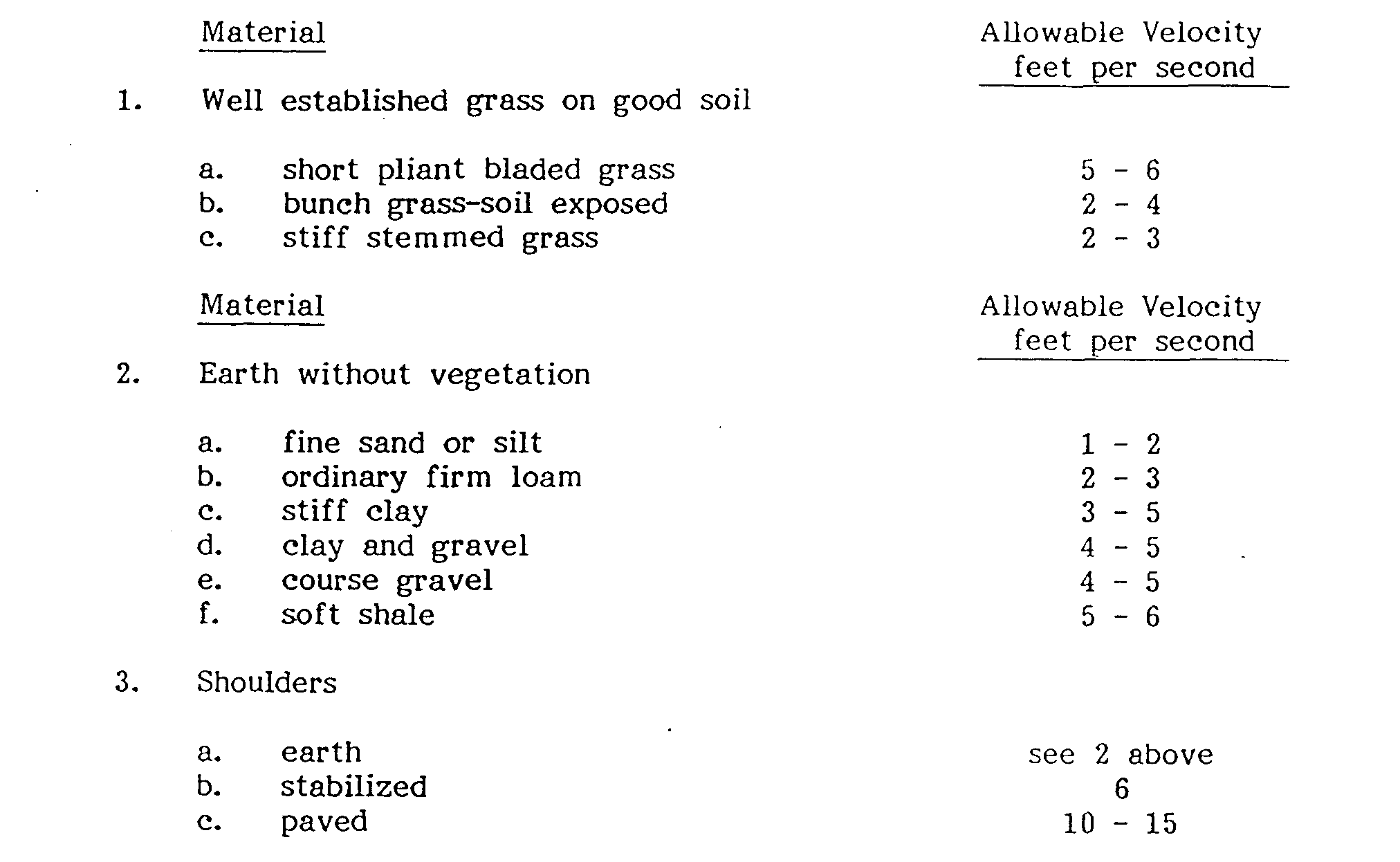
The maximum velocity as determined by Manning's equation shall not exceed the allowable velocities as shown in Table 3 for the specific type of swale material.�
Capacity of the swale shall be as shown in Figure G.�
3. Curbed Sections�
The maximum encroachment of water on the roadway pavement shall not exceed 4 inches in depth at the curb during a 10-year frequency storm of five minute duration (See Figure F).�
Inlets shall be provided to control the encroachment of water on the pavement.�
4. Inlets�
a. When there is a change in pipe size in the inlet, the elevation for the top of pipes should be the same or the smaller pipe higher. A minimum drop of two inches should be provided in the inlet between the lowest inlet pipe invert elevation and the outlet pipe invert elevation.�
b. If the capacity of the shoulder, swale, curb section or depressed median section exceeds the assumed inlet capacities, the inlet capacities shall govern the spacing of inlets.�
c. If the capacity of the shoulder, swale, curb section, or depressed median section is less than the inlet capacities, then the shoulder, swale, curb section or depressed section capacity shall govern the spacing of inlets.�
d. Type C Inlets�
i. This type inlet is designated for installation in nonmountable curbs. �
ii. It should be noted that inlets will operate more efficiently when they are spaced so that 5% of the gutter flow is permitted to bypass the inlet (95% efficiency). Therefore, 95% efficiency will be acceptable if 100% efficiency is not practical. �
iii. Inlet capacities shall be based on Figure 11 "Inlet and Gutter Flow Curves".�
iv. The capacity of an inlet at a low point of a street vertical curve may be designed to accept 4.0 efs from each direction or a maximum of 8.0 efs.�
e. Type M and S Inlets�
i. Type S Inlets are designated for installation in shoulder swale areas with back slopes 6:1 and steeper. Type M Inlets are designated to be used in swale areas where the back slope is flatter than 6:1.�
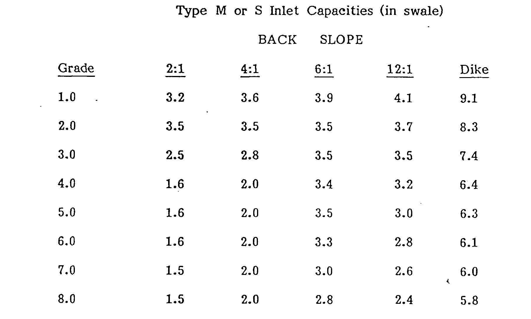
ii. Inlet capacities shall be based on Table 4 "Type M & S Inlet Capacities". �
iii. Where a drainage dike is used the side slope of the dike shall be 8:1 or flatter.�
iv. The capacity of an inlet at a low point in the swale (sump condition) is a 16 efs maximum.�
5. Storm Pipes�
a. To facilitate the solution of Manning's Equation as applied to storm pipes, charts are presented in "Design Charts for Open Channel Flow" prepared by the U.S. Department of Commerce, which permit a direct determination of the capacity of circular pipes.�
b. Where headroom is restricted, equivalent pipe arches may be used in lieu of circular pipe.�
c. The minimum diameter of storm pipe shall be 18 inches.�
d. Storm pipes will be provided in 6 inch increments of diameter.�
e. Abrupt changes in direction or slope of pipe shall be avoided.�
Where such abrupt changes are required, an inlet or manhole shall be placed at the point of change.�
f. The minimum slope in a pipe shall provide a minimum velocity of 2.5 fps. but, shall not have a minimum slope of less than 0.5%.�
g. The top of storm pipes shall be at least six inches below sub-grade elevation, except cast iron pipe, which may be within 3 inches.�

